A three-way switch enables control of a ceiling light‚ fan‚ or fixture from two locations‚ enhancing convenience and flexibility. Understanding wiring diagrams is crucial for safe and effective installation‚ ensuring proper connectivity and functionality. This guide provides a clear‚ step-by-step approach to wiring three-way switches‚ helping you master the process with confidence.
Understanding the Basics of Three-Way Switches
A three-way switch is a type of electrical switch that allows control of a light fixture or appliance from two different locations. Unlike a single-pole switch‚ which controls a fixture from one location‚ a three-way switch operates by connecting two switches via traveler wires. The basic components include a common terminal and two traveler terminals. The common terminal is connected to the power source or the fixture‚ while the traveler terminals connect the two switches. This setup enables the switches to work in tandem‚ allowing the fixture to be turned on or off from either location. Proper wiring is essential to ensure functionality and safety. Understanding the role of each terminal and wire is crucial for successful installation. Always use a wiring diagram specific to your setup to avoid errors. Testing voltage with a multimeter can help verify connections. Grounding is also critical for safety. By mastering these fundamentals‚ you can confidently install and troubleshoot three-way switch systems.
Key Components of a Three-Way Switch
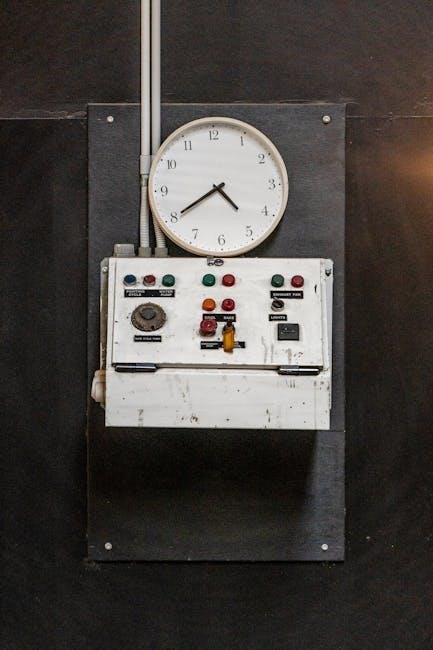
A three-way switch includes a common terminal‚ two traveler terminals‚ and a ground terminal. It requires a hot wire‚ neutral wire‚ and ground wire for proper functionality and safety.
Identifying Terminals and Wires
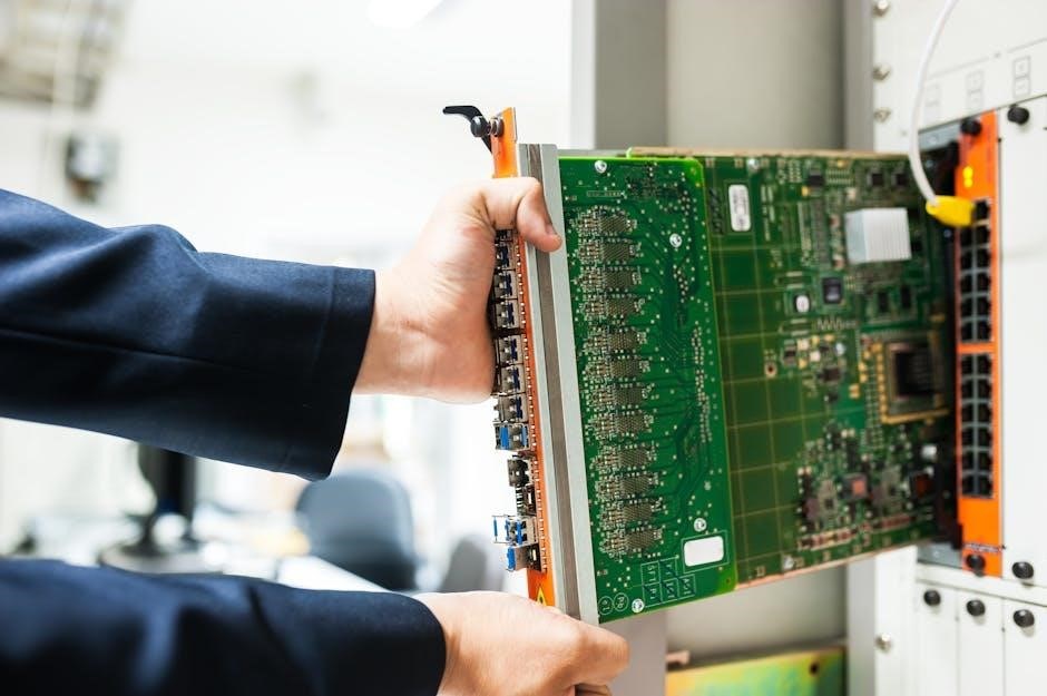
Identifying terminals and wires is essential for proper three-way switch installation. A three-way switch typically has three terminals: the common terminal‚ two traveler terminals‚ and a ground terminal. The common terminal is usually brass-colored and connects to the hot wire or the load. The traveler terminals‚ often black or brass‚ are used to connect the two switches. The ground terminal‚ usually green or bare‚ ensures safety by grounding the circuit. The wires involved include the hot wire (black)‚ neutral wire (white)‚ and ground wire (copper or green). Properly identifying these components ensures safe and correct wiring. Always use a voltage tester to confirm live wires before working. This step is crucial to avoid electrical shocks or short circuits. Understanding these connections is the foundation for successfully wiring a three-way switch setup.
Common Wiring Configurations for Three-Way Switches
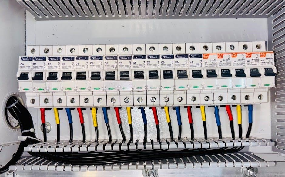
Three-way switches are commonly wired in two configurations: with power at the switch or at the fixture. Both setups require proper identification of travelers and common terminals to ensure functionality and safety.

Wiring Diagram with Power at the Switch
In this configuration‚ the power source connects directly to one of the three-way switches. The neutral wire is spliced through to the fixture‚ while the hot wire is connected to the common terminal. Traveler wires link the two switches‚ allowing them to control the fixture from both locations. Proper grounding ensures safety‚ and all connections must adhere to local electrical codes. This setup is ideal for new installations where power is accessible at the switch location. Always use a multimeter to verify live wires before proceeding. Ensure that the common terminal is correctly identified and wired to maintain the circuit’s integrity. Following a detailed wiring diagram is essential to avoid errors and ensure reliable operation of the controlled fixture.
Wiring Diagram with Power at the Fixture
This configuration places the power source at the fixture‚ with the switches controlling the circuit. The neutral and ground wires connect directly to the fixture‚ while the hot wire is routed through the switches. Traveler wires link the switches‚ enabling control from either location. The common terminal on each switch connects to the traveler wires‚ ensuring the circuit operates correctly. Properly identifying and connecting the wires is critical to avoid electrical hazards. Use a multimeter to verify live wires before starting. Ensure all connections are secure and meet local electrical codes. This setup is ideal for retrofitting or when power is already at the fixture location. Always follow a detailed wiring diagram to maintain safety and functionality. This configuration ensures reliable control of the fixture from both switches‚ providing convenience and efficiency.
Safety Tips and Precautions

Always turn off power at the circuit breaker before starting work. Use a voltage tester to ensure no live wires are present. Secure all connections tightly to prevent arcing. Follow local electrical codes and manufacturer instructions for safe installation. Ground wires must be properly connected to ensure shock protection. Never work on live circuits‚ and keep tools insulated to avoid accidents. Proper safety practices are essential to prevent injuries and ensure reliable functionality of the three-way switch system.
Essential Tools and Materials Needed
To successfully wire a three-way switch‚ gather the necessary tools and materials. A voltage tester or multimeter is crucial for identifying live wires and ensuring safety. Wire strippers are needed for preparing wire ends‚ while needle-nose pliers help with wire manipulation. A screwdriver set‚ including Phillips and flathead‚ is essential for switch and fixture connections. For materials‚ use 12-3 or 14-3 gauge wire with ground for inter-switch connections‚ depending on local codes. Wire nuts or connectors are required for secure wire splicing. Ensure all wires are properly insulated and grounded to prevent shocks. A junction box may be needed for housing connections. Always use UL-rated materials and follow NEC guidelines. Safety gear‚ such as insulated tools and goggles‚ is a must for protecting against electrical hazards. Proper tools and materials ensure a safe‚ efficient‚ and compliant installation of your three-way switch system.
Troubleshooting Common Issues
Use a voltage tester to identify live wires and ensure proper connections. Check for loose wires‚ incorrect traveler assignments‚ or faulty switches. Verify all grounds are securely connected to avoid shocks or malfunctions.

Identifying and Resolving Voltage and Connectivity Problems
When troubleshooting three-way switch wiring‚ start by using a voltage tester to identify live wires. Ensure the power is off at the circuit breaker before working. Common issues include incorrect traveler wire connections or loose terminals. Verify that the common (black) wire is properly linked between switches. If the light flickers or doesn’t turn on‚ check for faulty switches or poor wire nuts. Use a multimeter to test for continuity and voltage drops. Ground wires must be securely connected to prevent shocks. If the circuit doesn’t function‚ inspect the wiring diagram to confirm proper configuration. Power at the switch or fixture determines the wiring layout‚ so ensure your setup matches the diagram. Always double-check connections and test the system step-by-step to isolate and resolve issues efficiently.
Mastering three-way switch wiring requires patience and attention to detail. Always follow safety guidelines and verify connections with a voltage tester. For further learning‚ consult detailed wiring diagrams and guides from trusted sources. Additional resources include eBooks on electrical wiring‚ online tutorials‚ and forums where professionals share tips. Troubleshooting sections in manuals can also provide insights into common issues. Remember to use proper tools like multimeters and voltage testers for accurate diagnostics. Practice on a small project before tackling complex setups. With persistence‚ you’ll gain the skills to wire three-way switches confidently and safely.
- Refer to wiring diagram PDFs for visual guidance.
- Consult electrician forums for real-world solutions.
- Invest in a multimeter for precise voltage testing.